
Ultrasound can be effectively used for predictive and condition based maitnenance for detecting rubbing, lubrication, leaks, bearing and gear faults. It can also be used for detecting arcing in electrical equipment’s.
Overview
Sound waves with frequency over the human audible frequency range are called ultrasound. These are sound waves that have a frequency of 20 kHz and above. Ultrasound is short waves with low energy. Due to this ultrasound cannot travel for long distances or through objects, they are easily attenuated. But since they have a short wavelength (high frequency) they are directional. It is easy to filter them out from other acoustic signals and locate their source. This property of ultrasound makes it a perfect technology for some use cases in predictive maintenance.
Though it does not totally eliminate the use of vibration monitoring (0-10kHz), it definitely can augment the predictive capabilities. It also has an advantage that faults are visible in the ultrasonic spectrum (>20kHz) much earlier than in the vibration spectrum(0-10kHz). Airborne (one that is traveling in the air) and structure bound (that is traveling in a material e.g. pump casing) ultrasound can be used in different use cases.
Ultrasound vibration monitoring can be the first line of defense to effectively identify the following machine faults or defects:
- Early-stage bearing defects
- Lubrication issues – both over and under lubrication
- Leak detection in pressure and vacuum systems
- Steam trap, valves, seals and gaskets leak detection
- Corona, arcing and tracking in electrical systems
- Low RPM (up to 1 RPM) assets predictive maintenance
How do you measure Ultrasound?
Ultrasound is measured using a sensor which is a microphone in case of airborne ultrasound. In the case of structural born detection, a piezoelectric or MEMS sensor is used. When ultrasonic sound waves fall upon the resonant sensor it produces a small electrical charge. The sensor electronics amplify and measure this charge. While selecting a sensor the following needs to be considered:
- Signal to Noise Ratio (SRN)
- Sensitivity
- The frequency range
- Resonant frequency
Ultrasound is a very good go-no-go tool for predictive maintenance. It can give you a very early indication of developing faults. Once you detect issues with ultrasound you can further investigate the vibration spectrum. It is also a very good diagnostic technique to identify lubrication issues. Lubrication issues solved in time can prevent further damage to bearings and rotating parts.
Using ultrasound for identifying bearing faults and lubrication issues
There are two key ways to use ultrasound for the bearing and lubrication faults:
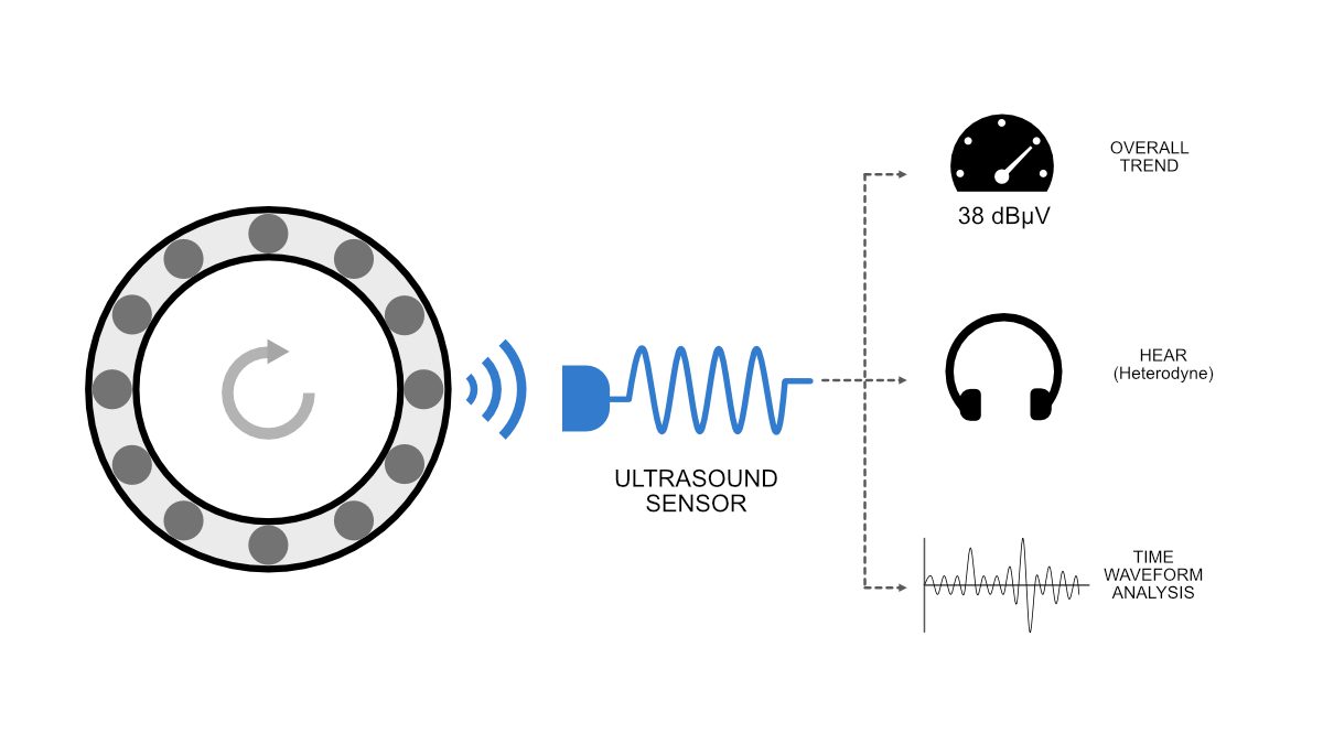
- Trending overall (static) measurements
- Waveform (dynamic) analysis in time or frequency domain
Overall Measurements
Overall ultrasound levels are easy to measure, interpret, and trend. Mostly the following two overall measurements are considered for ultrasound:
- RMS
- Peak
For ultrasound overall measurement decibels per microvolt (dBµV) or decibels (dB) measurement units can be used. The decibel (dB) is a relative unit that is usually quoted against a reference. It usually provides a change from a value e.g. +1dB. The Decibels can also be represented as an absolute measurement in reference to a fixed reference.
A suffix that indicated the reference value is added to the decibel (dB) symbol in this case. For example, if the reference value is 1 µV, then the suffix is “µV” is added and the unit becomes decibels per microvolt (dBµV). You can also interpret this in a different way, Decibel (dB) is the power level above one milliwatt while dBµV is voltage expressed in dB above 1µV into a specific load impedance. This is the relation between dB/dBm Vs dBµV:
dB + 10 log (Z) + 90 = ()dBµV Note: commonly we use 50 ohms Impedance
E.g 30 dB with 50 Ohm impedance is equal = ~137dBµV
Each unit has its pros and cons. For structural ultrasound decibel (dB) can be used for airborne ultrasound (dBµV) should be used. The choice depends on the analyst’s experience and also on what the sensor provides. With dBµV, you have the advantage of changing sensors or equipment for measurement; without worrying about an error in comparing measurements taken across different makes of sensors.
The RMS, which represents energy in the measurement band, is usually a good indicator of the problem but trending both is always better. It is important to understand that when using overall measurements establishing a baseline is the most important criterion. Most alerts are set as a change from this baseline. It is also important that when you replace sensors they should have similar characteristics of SRN, Sensitivity, and Resonance Frequency. In case they vary there might be an abrupt change in the levels and baselining may have to be done again. This would lead to all historical data being rendered unusable.
| Absolute change over baseline* | Fault Indicated |
|---|---|
| 8 to 10 dB | Poor lubrication or early bearing fault |
| 10 to 15 dB | Stage 2 bearing fault |
| 15 to 30 dB | Late-stage bearing faults |
| > 30db | Bearing failed |
*At slow speeds (RPM) there might not be any significant changes in dB levels so measuring ultrasound spectrum is very important for detecting bearing defects.
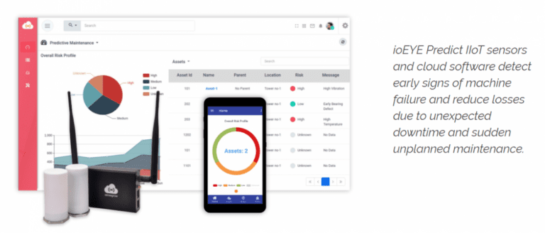
The ioEYE Predict IoT Vibration and Ultrasound Sensor can be used for trending the overall ultrasound vibrations.
Time Waveform Analysis
Time waveform analysis is the analysis of the ultrasound signal in the time domain. For ultrasound defect analysis, this is the preferred method over FFT analysis. In the early stage of the defect, there would be impacts visible in the time domain. In later stage defects, these impacts would occur at a periodic interval. The duration of the impact would correlate with the defect frequency of the bearing. Ultrasound signal of a defective bearing is strongly impulsive. It lacks any periodic (sinusoidal or repetitive) nature. They consist of a series of sharp impacts.
The above graph in time domain shows a periodic impact occurring every 0.1 sec. Which corresponds to the outer race defect frequency of the bearing. The amplitude of the impact is a good indication of the severity of the fault.
Spectral or FFT Analysis
FFT should be used as an analysis tool in case of repetitive signals (e.g. sinusoidal) with not very distinct peaks (i.e. when the deviation from the mean value is small). Ultrasound signal of a defective bearing is strongly impulsive and lacks any periodicity. They are transient signals with distinct impact peaks and low energy levels. This makes it difficult to analyze ultrasound signals of defective bearing in the frequency domain. FFT of such a signal would mask most defects. Though FFT can also be used in cases where the ultrasound signals do not have very distinct peaks e.g. in cases of the corona, arcing, and tracking in electrical systems.
Advantage of Ultrasound in Low RPM applications
There are three key problems with monitoring low RPM (less than ~600 RPM) rotating machinery:
- The amplitude (g level) of vibration produced by low RPM machines is so small that you require an accelerometer with high sensitivity. You require accelerometers with 500mV/g (pre-gain amplification) or better sensitivity.
- Most of the defect frequencies are within the 0-50x multiplier of the RPM. When RPM is low, like 1Hz, this could be a very low-frequency band of 0-50Hz. Measuring small accelerations at this low frequency is difficult due to electronic and FFT noise. These noises are more prominent in the lower frequency.
- Integrating the acceleration measurement to achieve velocity increases the noise. This makes measurement of velocity difficult in low RPM machines.
If you want to measure vibration (acceleration and velocity) in low RPM machines you would require a very sensitive accelerometer and will have to capture data at a very high LOR (Line of Resolution). Increasing LOR means that the number of samples collected would increase. This requires more memory and the duration of data collection increases. If not impossible, this is expensive and difficult to achieve in the field due to the increased cost of equipment and man-hours required to capture the data. The better alternate to this is ultrasonic measurement.
Ultrasound does not require measurement in multiple of the RPM. Why? Ultrasound is usually produced by either friction (two things rubbing together) or by turbulence (e.g. air leak) so we can easily detect these with ultrasound. Bearing defect and lubrication issues produce frictional and impacting acoustics (sound) in the ultrasound band, irrespective of the RPM of the machine. Since it is in the higher frequency band it does not require slow sampling and therefore the duration of samples is substantially smaller when compared to vibration measurement.
Usually, for the bearing defects, the frequency band of 35kHz to 45kHz is monitored. Most equipment will heterodyne the ultrasonic band of interest into the audible band. These can be listened to for impacting and bearing noise on a headphone or stored as an audio file to process them further in time and frequency domain.


2 Comments
Comments are closed.